Posts

Routing PVC Hexagons

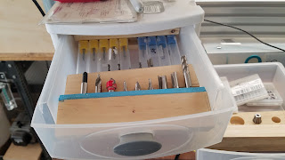
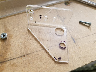
ROUTING PVC While working on a trophy project I learned a lot about cutting PVC on the CNC. Generally the stuff cuts like butter, is strong and can result in a smooth and rugged surface finish. I also successfully finished it with custom custom acrylic colors. THE MATERIAL PVC (Polyvinyl Chloride) Sheet, Opaque White, Standard Tolerance, UL 94/ASTM D1784, 1/4" Thickness, 12" Width, 24" Length THE BIT I used a compression bit for the first time and it worked well. These up/down bits are inexpensive: https://www.amazon.com/gp/product/B073RKCWGH/ref=oh_aui_search_detailpage?ie=UTF8&psc=1 I would expect that this OnSrud 63-703 bit would also work well and since it is 1/16 will remove less material. It is however more expensive. THE SPEED Spindle: Feed Rate: 30ips TABS: I tried tabs but would not recommend them unless you want to do a lot of cleanup. The tabs are hard to file off while keeping a smooth finish. I use tape to hold the material to the

Battling Electrical Noise in CNC builds

 Electrical Noise in CNC builds I recently posted my design guidelines for electrically noiseless builds on another blog and am sharing it here. https://donsthings.blogspot.com/2018/09/battling-electrical-noise-in-cnc-builds.html Donate: Please consider donating (button to the lower left of this post). Your donations help fund additional research, experiments, designs, tools and parts that I will return to the community as information. Enjoy and comment, Don

Chomping at the Bit

Image
Bits Everywhere! I got tired of chasing my bits around the surfaces of my CNC and decided to organize them. Now I have a 3 drawer chest that holds my bits in separate wooden sections organized by bit type. I plan to mark the bits with #'s that correlate with my tool library in F360. I wanted to keep the holders that come with some bits because I like how they protect the bit. For these cases I glued the bottom of the holder into a slot I milled into the wood holder. I found that gluing a piece of foam at the top edge of the holders help to keep the bits from falling out. We will see if this solves my problem :). Enjoy and comment, Don

Dust Extraction 1.0

Image
Dust Shoe and Hose Management Designs There are many dust shoe designs both commercial and DIY for dust extraction in a CNC. Mostly I do not like that the dust shoe seems to be in the way and it blocks the view of the bit. Perhaps as I become more confident with my CNC programming I will not care if the bit is visible. Furthermore the vacuum hose designs I reviewed were quite complex and generally put stress on the gantry.  I set out to see if I could design/build something simpler and easier to use. Prototype Dust Shoe I decided to see if I could build a plenum that attached to the spindle bracket and pull air from around the bit. This would be simple to adjust up/down and simple to get on and off without obstructing the view of the bit.  I postulated that if the orifice at the bit was kept close enough and the velocity high enough I could pull away most of the chips. Alternately I could add air to try and blow the dust toward the vacuum plenum. In the prototype below

A Simpler Spoil Board?

Image
SPOIL BOARD Google'ing shows that there are a gaggle of spoil board configurations out there. Since my initial build I have been using a spoil board made of particle board with routed T-slots. I used a secondary T-slot board to increase the holding options. This spoil board was made from two sheets of particle board with milled T-slots. The two board were joined in the middle using a lap joint cut on my router. This was material that I had yanked from someones pile of kitchen refinishing remnants. The upper spoil board was also made from particle board with T-slots milled transversely. Practical Work Holding I mostly have been working routing wood and that has driven me to use a different work holding method. The following approach will not work for milling metals at least not anything robust. Tape as a Work Holding Medium After many frustrations hitting the clamps used in traditional work holding ) using a variety or T-clamps) I investigated using tape as a hold

OX 48V spindle control

Image
Background DRAFT WORK IN PROGRESS One of the first steps in setting up the OX for operation is to calibrate the spindle speed vs the "M3" values sent from the TinyG. My first set of tests revealed a non-linearity in this control function. https://plus.google.com/+DonKleinschnitz/posts/AG6gZ7Lxhs7 This caused me to start a search to find, explain and remove the spindle vs speed linearity, the subject of this post. Donate: Please consider donating (button to the left bottom of this post). Your donations help fund additional research, tools and parts that I will return to the community as DIY information. Circuit tracing The Rio Rand controller was dissembled and a schematic was created. Theory of operation The key elements of the controller's design are: PWM input source choices: external or internal generated PWM selected by jumper External PWM: an opto-coupler interfaces the external PWM to the 555 which in this mode is used as a pre-st

Zaxis endstops

Image
End-stops for the Z axis Whenever you label a design with something like "Universal"  Endstop Bracket  your asking to be taught that nothing is "Universal". Such was the case with designing Z axis end stops for my OX. I needed a micro-switch on the top and the bottom of the Z axis's travel. There was no place to mount the simple "universal" brackets up in that very busy Z axis mechanism. Since these brackets were essentially made on the fly, lots of trial and error, I do not have drawings for them. The parts were made from both .093 and .22 acrylic and bent on a shop made hot wire bender. Oh, and a dab of superglue here and there. Down End-stop The down end-stop is mounted on the upper Z channel top plate just below the Z stepper. I wanted to mount it on a stationary part of the mechanism and let the switch be activated by the moving axis. That approach eliminates wires having to move but there was no room. So I ended up moving the switch