OX 48V spindle control
Background
DRAFT WORK IN PROGRESS
One of the first steps in setting up the OX for operation is to calibrate the spindle speed vs the "M3" values sent from the TinyG.My first set of tests revealed a non-linearity in this control function.
https://plus.google.com/+DonKleinschnitz/posts/AG6gZ7Lxhs7
Donate:
Please consider donating (button to the left bottom of this post).Your donations help fund additional research, tools and parts that I will return to the community as DIY information.
Circuit tracing
The Rio Rand controller was dissembled and a schematic was created.
Theory of operation
The key elements of the controller's design are:- PWM input source choices: external or internal generated PWM selected by jumper
- External PWM: an opto-coupler interfaces the external PWM to the 555 which in this mode is used as a pre-stage driver to the motor driver MOSFET. The input signal levels are specified at 3.5-5vdc. My static analysis shows that the TinyG should drive the opto-coupler fine although I would prefer a higher voltage interface for noise immunity reasons.
- Internal PWM: a NE555 timer is configured as an astable mode oscillator whose duty cycle is controlled by adjusting the charge-discharge values using a diode network and pot. Adjusting the Duty Factor (DF) changes the PWM pulse width and in turn the motor's speed.
- Low voltage power supply: a full wave rectifier ensures that the broad range of AC/DC input is converted to DC. The DC is filtered and then regulated to 12V by a series pass regulator and 12V zener. This voltage is used to power the opto-couplers open collector output and the 555. Input power values below the specified 12V do not regulate and therefore can cause variation in the motor's speed and control. The power input is fused.
- Motor driver: The motor is driven by a 500V 20A MOSFET (@25C)
- Noise immunity: Reasonable care is taken in the design to suppress noise and protect parts against flyback. The input is also fused.
Rio Rand Design Observations:
The Rio Rand controller supports a broad input voltage range for both DC and AC voltages. I see the value of this ability for spindles that run high voltage like the popular water-cooled 110V 800W spindles. However there seems to be a mismatch? The common US power is nominally 120V and the typical 800W spindle is 110V. This may result in over-driving 800W spindles.I do not plan to test this controller at high voltage unless someone donates a 800W spindle motor :)
Overkill for 48 vdc Applications:
It is my opinion that this design is overkill for driving 48vdc spindles. The Rio Rand's AC rectification and subsequent regulation circuits are not necessary for remote TinyG control for 48 vdc spindles.
Furthermore, the internal 555 PWM generator is not necessary if remote TinyG control is being used.
I will admit that sometimes its nice to directly control the PWM but if needed I would control that by switching in a known PWM signal. The internal PWM of the Rio Rand controls the speed but the PWM value used and its relation to speed is hidden.
The advantage of simplifying this design is that it can more easily mount near the motor and would be more reliable. Running the output of the motor controller through the wiring harness is not a good idea because it is a source of high current noise. This may be the reason so many builders have noise problems with endpoint switches.
My future plans include designing (purchasing) a driver that meets these OX 48 vdc spindle specific specs:
- Switch between two external PWM sources both optically isolated
- Built in motor DVM
- 48vdc only operation
- Integrated heat sync
- Integrated extrusion mounting
- Optional fan...
- Test points.
Note: if I go to a higher power spindle (currently 400W) it will probably be a Dewalt and I will give up remote speed control.
Test Setup
Two Rio Rand controllers were employed in these tests, one on the bench run @ 24vdc and the other installed in my OX run at 48 vdc.
- Controller #1 is installed in my OX and uses a soldered in speed pot.
- Controller #2 is used for bench testing and uses a plug in speed pot.
Test equipment
Three scopes were used at various times:- RIGOL DS1102E
- Textronix 465
- DSO150
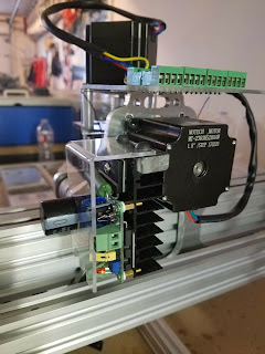
 |
| Bench setup |
Test Plan
Testing will be completed as follows:
Bench test
Completed: Verify the controller theory of operation using controller #2.
- Weak DC internal regulation at voltages below 18V. Impacts PWM frequency and speed vs PWM value. Likely results in non-linear pwm vs speed at <18V input power levels.
- PWM Freq: 2.55Khz @24vdc
OX test
Map signal level, voltage, and frequency values from the TinyG through the system to the motor drive. Controller #1 is installed in the OX


- Verify integrity of TinyG input drive through opto-coupler
- Completed: signal quality is good at the output of the opto-coupler
 |
| Opto-coupler output |
- Verify linearity of TinyG M3 values vs PWM values
- Completed: initial results show that actual PWM value closely tracks the calculated PWM values for the p1csh settings. The source of non-linearity is not the TinyG
- Not sure I still understand the phase settings p1cp(x). Apparently others are confused since I found a lot of discussion in various searches none of which provided a clear explanation of how they are used. I gather that these values are the allowable low and high DF values that the TinyG will use when creating a PWM signal. Example: .2 and .9 settings will result in PWM values only between 20% and 90%. I also gather that the PWM will be linear-ized between these values? Correct. No? I did not test this theory.
- Verify motor operation to 100% DF (PWM=1)
- Completed: motor stopped at 11,400 with p1csh =12,000 rpm
- Discovered that TinyG stops sending a PWM signal within 500 rpm of p1csh setting. Changed setting to 13,000 rpm and now the PWM will run to 100%. Although this modified the linearity some it does not seem significant. Since this is firmware generated I do not understand why it is not more accurate? Seems a setting or 12,100 for p1csh would allow a M3 S value of 12,000?
- Verify motor voltage vs DF
- Problem found: the motor voltage @ M3 S6000 is already at 43 vdc vs the calculated value of 23 VDC. This creates a significant offset in the motor's speed i.e. @ M3 S6000 the motor is running 11,322 rpm.

- Examining the motor voltage vs PWM input shows that @ 50% DF the PWM signal is correct, the motor turns on properly (drain goes to gnd), turns off properly (goes to 48vdc) but then turns back full on during the off period of the PWM signal. What is causing the driver to turn back on?

- Test controller # 2 on the bench @50% DF to see if it has the same behavior?
- Completed: controller #2 does not exhibit turn on/off problems at 50% DF

Controller #2 switches closely on/off with internal PWM running at 50% DF. - Test controller #1 at various DF to see if that reveals a hint.
- The blue tape shows the M3 Svalue.
- Channel 1: Gate of the drive transistor.
- Channel 2: drain of driveMOSFET. Gnd means the MOSFET it turned on.
- Scope traces show that the driver turns on OK during the PWM on cycle. However, during the off cycle, it turns back on at various levels depending on the DF on its gate. This clearly explains why the speed vs DF is incorrect.


- Uninstall controller #1 and test on the bench to see if it still exhibits this behavior.
Enjoy and comment
Maker Don


Appreciation for really being thoughtful and also for deciding on
ReplyDeletecertain marvelous guides most people really want to be aware of.
Pulse Oximeter manufacturer
pulse oximeter supplier
Pulse Oximeter manufacturers
The young boys ended up stimulated to read through them and now
ReplyDeletehave unquestionably been having fun with these things.
bmi machine manufacturer
bmi machine supplier