DOX Power & Controller Module
Electronics Packaging
I had the following goals for the DOX electronics packaging:
- Modular, easy to wire, troubleshoot and repair
- Minimize length of power wiring
- Visibility of the controller lights
- Easy access to the USB plug
- Fuse protection
- EStop provisions
- Easy to access screw terminals on TinyG
- Provision for cooling
Materials & parts:
- Base plates: .22 acrylic from Home Depot
- EStop frame: .22 acrylic from Home Depot
- Cover: .093 acrylic from Home Depot
- Black standoffs: 3/4x 3/4 acrylic standoffs. Scraps from pen turning
- Power Supplys: came with OX kit.
- Controller: TinyG
- Wire: various mostly from strippin old power cords
- EStop Switch: Red Mushroom Cap 1NO 1NC DPST Emergency Stop Push Button Switch AC 660V 10A
- Terminal strip: 600V 15A 6 Position Double Row Screw Terminal Strip
- AC input plug: AC 250V 10A IEC 320 C14 Panel Mount Plug Adapter Power Connector Socket
- Inline blade fuse holders: Wallmart auto dept
Special Tools:
- Shop built acrylic bender
The Build

The electronics is packaged in an acrylic box that is bolted on top of 2x power supplies (24 & 48VDC) resulting in a single module that contains all power/control and wiring. The main power is supplied through a modular EStop switch.

The controller container was a fabrication experiment. I designed it on SU (see link below) which outputted a pattern that could be bent on the acrylic bender. The simple square pattern has the corners cut out so that the sides of the could be bent to form a cover. This technique was simple and worked great resulting in a single piece cover with no gluing. This technique results in corners that are not closed but that is ok for this application. This approach also allowed the use of lightweight plastic (.093).
The cover is affixed by using 4 spacers (black) that are mounted on the controller base plate. The controller base plate is screwed to the top of the power supplies using the threaded holes in the power supply frames.
The controller is mounted such that the USB cable is on the front and stepper and end stops wiring enters through strain reliefs in the back.
The LEDs on the TinyG are visible through the cover.
The board is mounted on standoffs and the standoffs are screwed to the plate using heat insert threaded adapters from McMaster Carr.
The 30 x 30 x 10 mm fan that came with the kit was mounted above the stepper drivers by inserting heat insert threaded adapters into two opposing corners so that it could be mounted to the cover from above.
I will mount a filter material to the fan input at a later time. I may also add more fans if necessary.

The 30 x 30 x 10 mm fan that came with the kit has two pins and the plug for on the TinyG has three. I cut off the stock connector and added a two pin. It does not have an orientation lock :(, so I labeled the +/- on the connector. Note the 24vdc connection that comes from the PS below through the plates.
 |
| Left side view |
 |
| Front view. PS is oriented so that the fan faces out. |
 |
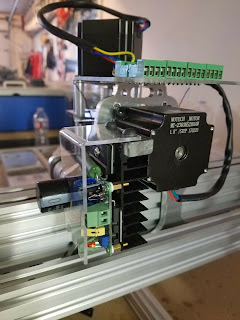
| Back side view. Fan facing out, DC terminal block, short wires for the 24 vdc to controller. 48 vdc wire to run to spindle driver. |
 |
| Right side view. PS I/O wiring. Note single point grounding and DC power inline fuses. The PS leds are also visible from this side. |
E Stop
The EStop switch is mounted in a single piece bent acrylic (.22") frame and a AC cord pigtail connects it to the controller module. This way the EStop can be dynamically located anywhere on the front edge surface of the DOX table.
The EStop switch only removes AC input power so its not really a "real" EStop. I have provisions to add a relay to this frame which would also remove 24/48vdc power. I plan to see how fast the motors will spin down under load and then make a decision on adding the relay.

Design Models
- Schematic: The AC/DC wiring has been added to the schematics that are linked in Wiring the OX
- The electronics packaging: Design can be found in the 3D warehouse.
Enjoy and comment,
Don
Don

Comments
Post a Comment