The Oxcellent Adventure Begins
Ready-Set-BUILD
My OX arrived from SMW3D today.SMW3D has been great! Extremely responsive, replaced a damaged part, answer all my questions and provide sound advice.
I would recommend their this kit.
Shipping, Packaging, Un-boxing and Inspection


 |
| Whoops.... SMW3D is on it! |
Documentation
The unit came with illustrated step-by step instructions
Observations:
1. Don't pull stuff out of the individual bags no mater how curious you are! The bags are nicely labeled by the steps that they pertain to. Pulling out the parts upsets the build sequence and will cause you to loose track of what parts go where. The documentation gives you an inventory of parts for each step enabling you to get them back in the right bag.
Online help:
This site is invaluable.
http://www.openbuilds.com/builds/openbuilds-ox-cnc-machine.341/
I highly recommend downloading the SketchUp model to use as a reference. The parts are not exactly the same as the kit but it provides a great "look around" perspective especially when you get disoriented. Its a great "big picture" view to go along with the instructions. Knowing this file existed at the start would have helped immensely.
Most of the comments and captions in this post are supplements to the instructions for things I tripped on.
Suggestions:
Be nice if the parts bags inside the step bags were also labeled with the step #, I did such.
Preparing to start
As we prepare to start step one. How many guys have a wife that would let them use the dining room table!

Step 1: The frame
The frame consists of 2x-20 x 80 and 4x-20 x 40 extrusions bolted on the edges with a 5 hole angle bracket.
 |
| Don't assemble like this with the wrong end rails. |
 |
| Should be like this |
Update: I found out yesterday that the frame is assembled wrong. Uggh ... we confused the end rails with the gantry rails. The 20-60's are for the gantry cross rails and the 20-40 are for the base. There is also one 20-40 that is the same length as the 20-60 that is used as a gantry rail.
Warning: Don't unpack the rails until you use them as they are matched and bundled together.
This correction did not effect the frame assembly the alignment instructions. The pictures below are still valid just mentally substitute the 20-40 rails for the 20-80 in the pictures below.
Correct pictures later....
 |
| I used my driver and a drill-tap to thread the holes in the 20x80 sides |
 |
| I borrowed this cutting stick from my machine shop's lathe |
 |
| This made tapping quick easy and accurate. |
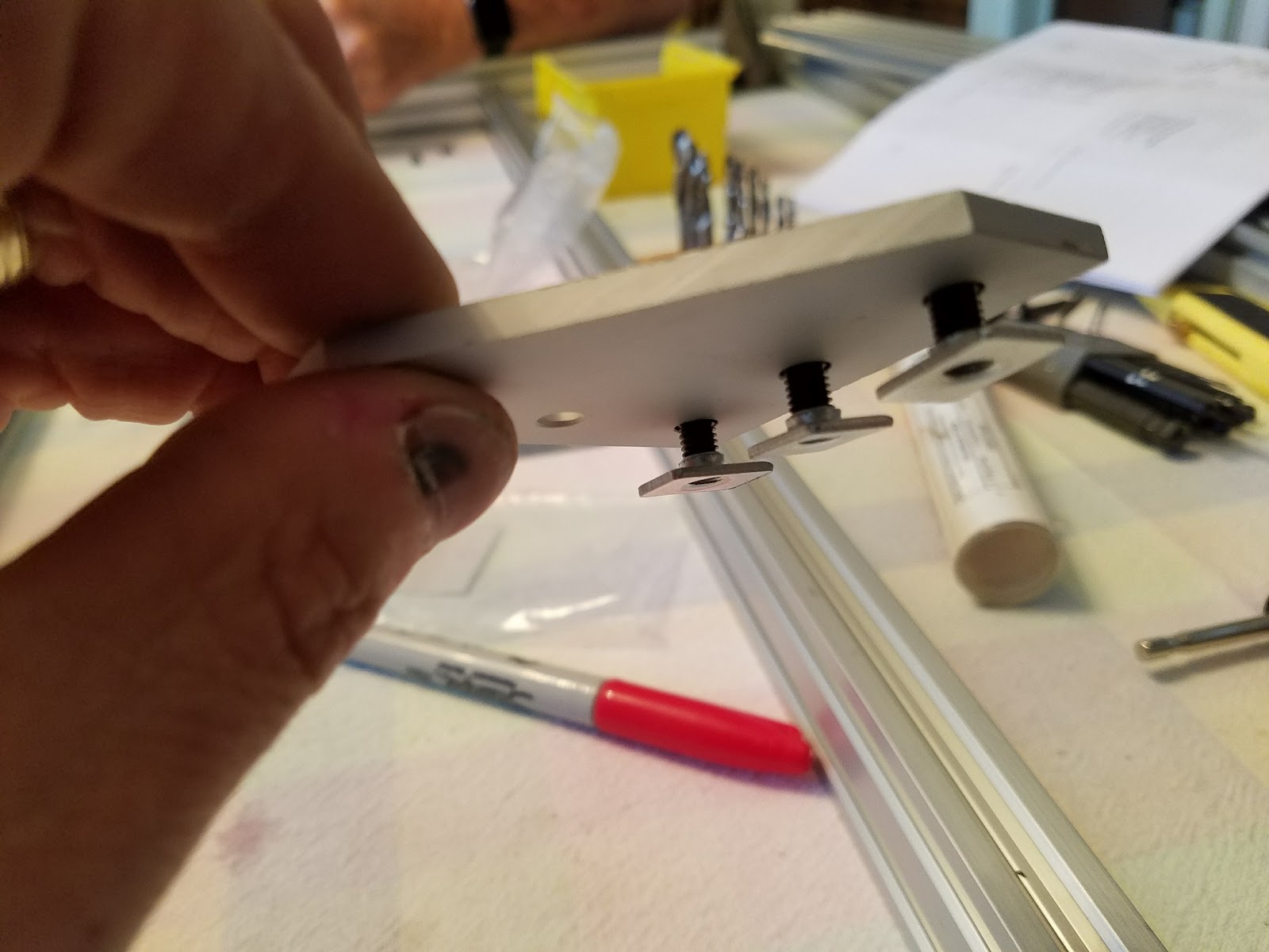 |
| I found that installing the 3x bottom screws into the 5 hole plate first makes the assembly easier. Nuts on back side |
 |
| Once the screws and nuts are installed on the 5 hole plate, slide it into the top slot of the 80-20 rail and snug up. |
Center braces
The center 80-40 braces were installed with one angle bracket on each end as the instructions inferred. It seemed that 2x brackets on each would be more appropriate and we had 2x left over? There were no clear pictures showing 2x installed so we installed one with the expectation that we may have to come back and add another later.
Update: indeed there should be two angle brackets. In the pictures below the cross braces are correct but the end rails are wrong, they should be the 20-40's not 20-60.
Update: indeed there should be two angle brackets. In the pictures below the cross braces are correct but the end rails are wrong, they should be the 20-40's not 20-60.
The 2x braces were installed 9 1/4" from the inside edge of the frame (1/3 spacing)


Step 2: Frame Adjustments
After the frame was assembled the 20-80 rails were "squared" to the 20-40 rails using a machinist square in each corner. After squaring the rails to each other we discovered that the entire frame was out of square by measuring the diagonal. I became clear that the 20-80 rails were parallel but the frame was out of square by 1/2". I did not know if the upper rails are parallel and the frame is not square it mattered. To be safe we proceeded to square up the frame by adding 4x (.044) shims, one in each corner. We got the entire frame square to less than 1/8 (across diagonals) after tightening and squaring everything.Shims were installed in all 4 corners 2 on the outside and 2 on the inside of the 5 hole plate. The shims were installed under the 3 screws between the 5 hole plate and the 20-60 extrusions. The pictures show the shims moving clockwise around the frame. Opposing corners should have the shims installed on the same side of the 5 hole plate.


Note on shims: the instructions said to "square everything" but exactly what to "square" other than the 20-80 rails was unclear. Using a level to square things seemed error prone so we used a machinist square to supplement measuring the diagonals. We concluded the the need for shims was driven by the end-cuts on the 20-80 rails being slightly off (1/32) and its amplifying effect across the long 20-80 rails.
Step 3: Gantry Wheel/End-plates
Wheel Kit
The instructions suggest finding a video for the wheel kit assembly. I used this one https://www.youtube.com/watch?v=6K2zyFUJyJ8. Each of the 14x wheel kits are assembled the same way but the placement of the "precision washers" was unclear. Especially the one that is not installed inside the wheel.
One precision washer goes inside the assembled wheel kit and one goes between the wheel bearing and the spacer during the install of the wheel into the gantry.
I found the the simplest assembly was:
- Assemble bolt-bearing-precision washer
- Press that into one side of the plastic wheel
- Press the other bearing into the other side of the assembly
- You will have a precision washer left after that step and it will be installed with wheel kit.

There are two types of spaces and all kits get spacers. The 4x wheels placed in the top of the gantry plate get "standard" spacers and the 3x bottom placed wheels get the "eccentric" ones.
The entire assembly with wheel kit installed in the gantry plates have components assembled in this order:
- Bolt
- Bearing
- Precision washer
- Plastic wheel
- Bearing
- Precision washer
- Spacer (eccentric on bottom group and standard on the top group)
- Gantry plate
- Nut
 |
| Lower wheel with eccentric spacers, note the precision spacer between the wheel bearing and the spacer. |
 |
| Upper wheel with standard spacers, note the precision spacer between the wheel bearing and the spacer. |
 |
| Nut on outside of gantry plate with no washer. |
Observations:
- The instructions are hard to visualize because the black anodized rails obscures the details and features tend to blend together.
- The 20-40 center rails need better pictures and clearer instructions on how many angle brackets are installed.
- The bearing kits should have a simple exploded assembly view and the directions of mounting should be clearer. (see "wheel kit" section above)
- Pictures that help to identify parts by the name used in the instructions would eliminate some guessing.
- Less words more assy pictures and exploded views :). Pictures of completed assemblies from various angles.
- Clearer indication when the parts in the instructions may be different from what is in a particular kit. i.e. steppers and extended vs standard kit parts.
- The steppers are to be installed with M5 x 25 mm screws. There were none this length in this steps bag of parts. Instead they were 20 mm in length which worked fine.
- The stepper nuts (installed on the stepper side of the gantry plates) are not captured so an open end wrench is necessary. The steppers should be tapped, or some better way to capture the nut so a wrench can fit on it.
Note: I got a copy of a new instruction manual and it looks like items 1,2,5 above have been substantially improved.
Step 4: Gantry Side Plates
I got stalled because the 20-40 cross members are two short for the gap between gantry plates.
Did I assemble something wrong?
The instructions say that the gap may be to tight by a bit, this is the opposite direction and seems excessive.
Update: As stated above we used the wrong rails for the end rails and cross members. Correcting this error took out some of gap but not all. Still working this problem.
The instructions say that the gap may be to tight by a bit, this is the opposite direction and seems excessive.
Update: As stated above we used the wrong rails for the end rails and cross members. Correcting this error took out some of gap but not all. Still working this problem.
 |
| Beam located to one side... |
 |
| Gap from beam to other side... |
After correctly assembling the frame there was still a gap. We adjusted the 20-80 rails inward to make up the gap.


Step 5: The Gantry
The gantry is surely the most complex assembly in the build and the pictures in the instructions were not as clear as they could be. An additional challenge was that I bought the extended options, larger steppers and max wheels. In all cases these parts and assemblies did not match the instructions.
We did not assemble the gantry around the gantry cross rails as we are still trying to figure out why they are to short.
Later I will add detailed text to this area but for now these pictures should go a long way in providing a clear perspective of how the parts of this version are assembled. Assuming of course I got it right :).
These pictures are not in the order that we assembled them.
A good video that shows mounting a Nema 23 motor and the acme assembly.
https://www.youtube.com/watch?v=phap4ZqYu1o
 |
| Model of the Z axis extrusion assembly note the standard spacers on one side and the eccentric ones on the other. |
https://www.youtube.com/watch?v=phap4ZqYu1o


 |
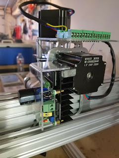
| Back view turned 90 showing rear nuts and motor mounting |
 |
| Z axis rail |
 |
| Motor mount spacers and acme/stepper coupling. The larger motor option (above) has a different plate and spacers than the standard |

 |
| Right side from back |
 |
| Underside of upper stepper plate showing locking collar and bearing |
 |
| Side view of bottom Z axis bracket showing acme screw, locking collar, bearing and plate |
 |
| View from bottom of z axis showing bottom plate and acme screw |

 |
| Side view of carridge assy. Note order of spacers and wheels |
 |
| View from bottom of gantry |
 |
| Gantry mounted on rails. View from right rear. With x and Z stepper mounted |
 |
| Front right view of gantry assembly on 20 x 60 rail |
 |
| Detail view of right front side of gantry showing eccentric spacers |
 |
| Left front side of gantry with standard wheel spacers |
 |
| Left side view of gantry with stepper mount and acme screw. |
Mounting the Spindle
Not sure if the angle brackets are best positioned upward or down? For now I put them facing inward to get the max down position of the spindle.


Comments
Post a Comment